Advancements in magnetic encoding technology have enabled the development of compact, low-cost encoders that are more tolerant of dirty and harsh operating environments where optical encoders could skip pulses.
The new magnetic encoder designs that use Hall effect technology to obtain high resolution from a durable magnetic target disc.Magnetic sensing does not need a clean transparent gap. Only some distance between the magnetic target and sensor is needed to operate properly.Dirt, dust, oil, condensation and other contaminants do not affect the reliability of a magnetic encoder.
AS5040
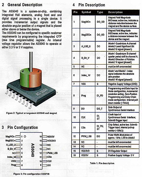
The AS5040 is a system-on-chip, combining integrated hall elements, analog front end and digital signal processing in a single device. It provides incremental output signals and the absolute angular position of a magnet that is placed above or below the device. This device is manufactured by austriamicrosystems.
The AS5040 can be configured to specific customer requirements by programming the integrated OTP (one time programmable) register. An internal voltage regulator allows operating the AS5040 device at either 3.3 V or 5 V supplies.
The AS5040 chip consists of a ring of hall elements placed at
the center of the IC in a circle of 2.2mm diameter. The hall elements pick up
the field of a magnet placed above this hall array. This information is
digitized and fed into a digital signal processor which calculates the angle of
the magnet with a resolution of 0.35 degrees or 1024 positions per revolution at
a sampling rate of 10 kHz.
The digital angle information is available in several formats;
as a serial 10 bit data stream, as a pulse-width modulated (PWM) signal or as a
quadrature incremental signal.
Physical Details
The chip itself is very small, measuring approx. 7.8 mm x
5 mm and has 16 pins and can be built up to replace the
potentiometers in many types of antenna rotators giving a far more
accurate and consistent readout than the original setup as there aren't
any mechanical contacts to wear. The only moving part is a
small rare-earth magnet 6 mm in diam. that needs to be attached to a shaft
and placed ~ 0.5 -5 mm above the AS5040.
Benefits
- Complete system-on-chip
- Flexible system solution provides absolute, PWM and incremental outputs simultaneously
- Ideal for applications in harsh environments due to contactless position sensing
- Tolerant to magnet misalignment and air gap variations
- No temperature compensation necessary
- No calibration required
Key Features
- Contactless high resolution rotational position encoding over a full turn of 360 degrees
- Two digital 10bit absolute outputs: - Serial interface and - Pulse width modulated (PWM) output
- Three incremental output modes: - Quadrature A/B and Index output signal - Step / Direction and Index output signal - 3-phase commutation for brushless DC motors- 10, 9, 8 or 7 bit user programmable resolution
- User programmable zero / index position
- Failure detection mode for magnet placement monitoring and loss of power supply
- Rotational speeds up to 30,000 rpm
- Push button functionality detects movement of magnet in Z-axis
- Serial read-out of multiple interconnected AS5040 devices using Daisy Chain mode
- Wide temperature range: - 40°C to + 125°C
- Fully automotive qualified to AEC-Q100, grade 1
- Small Pb-free package: SSOP 16 (5.3mm x 6.2mm)
Functional Description
The AS5040 is manufactured in a CMOS standard process and uses a spinning current Hall technology for sensing the magnetic field distribution across the surface of the chip.The integrated Hall elements are placed around the center of the device and deliver a voltage representation of the magnetic field at the surface of the IC.Through Sigma-Delta Analog / Digital Conversion and Digital Signal-Processing (DSP) algorithms, the AS5040 provides accurate high-resolution absolute angular position information. For this purpose a Coordinate Rotation Digital Computer (CORDIC) calculates the angle and the magnitude of the Hall array signals.The DSP is also used to provide digital information at the outputs MagINCn and MagDECn that indicate movements of the used magnet towards or away from the device’s surface.A small low cost diametrically magnetized (two-pole) standard magnet provides the angular position information.The AS5040 senses the orientation of the magnetic field and calculates a 10-bit binary code. This code can be accessed via a Synchronous Serial Interface (SSI). In addition, an absolute angular representation is given by a Pulse Width Modulated signal at pin 12 (PWM). Besides the absolute angular position information the device simultaneously provides incremental output signals. The various incremental output modes can be selected by programming the OTP mode register bits As long as no programming voltage is applied to pin Prog, the new setting may be overwritten at any time and will be reset to default when power is turned off. To make the setting permanent, the OTP register must be programmed The default setting is a quadrature A/B mode including the Index signal with a pulse width of 1 LSB. The Index signal is logic high at the user programmable zero position. The AS5040 is tolerant to magnet misalignment and magnetic stray fields due to differential measurement technique and Hall sensor conditioning circuitry.
Block diagram for AS5040 Rotary Encoder IC

Applications
- Industrial applications:
- Contactless rotary position sensing
- Robotics
- Brushless DC motor commutation
- Power tools
- Robotics
- Brushless DC motor commutation
- Power tools
- Automotive applications:
- Steering wheel position sensing
- Gas pedal position sensing
- Transmission gearbox encoder
- Headlight position control
- Power seat position indicator
- Gas pedal position sensing
- Transmission gearbox encoder
- Headlight position control
- Power seat position indicator
- Office equipment: printers, scanners, copiers
- Replacement of optical encoders
- Front panel rotary switches
- Replacement of potentiometers
No comments:
Post a Comment